1.4 Documentation
The vertical photo documentation included temporary reference points and scales and was supported by distance, size and height measurements relative to a datum point, taken with the underwater height meter (UHM) that had recently been developed (Botma & Maarleveld 1987). Although a pilot study (Hugen 1990) showed that a three-dimensional site model can be created from the documentation (fig. 7), the process of photogrammetric processing proved unduly cumbersome (Vos 2011 HyperlinkVOS). Even on land and in clear water, photogrammetry is not necessarily the most cost-effective documentation method (Reinders 1986). With software that integrates various ways of data capture and 3D modelling, it adds to the archaeological toolkit but is hardly ever a replacement (Green & Gainsford 2003; Sanders 2011). The main problem is that even in non-parametric approaches the accuracy of automated results is fully dependent on the accuracy of the input and the input that qualifies as archaeological documentation needs selective and consistent, time-consuming interpretation. Part of the disappointment with photogrammetry was that the amount of time, equipment and computer power needed for processing was not cost-effective and that outsourcing interpretative phases led to faulty interpretations.
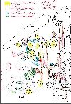
From the start, the vertical photographic pairs were complemented with oblique photographs of each individual cargo item to be removed. Individual items were identified on vertical photographs according to the imaginary grid. This obviously was done on land and in order to reduce precious bottom time. A label and a labelled photo assignment for one or more oblique shots of the same item were then prepared along with a slate with its sketched position, to be taken down on the next occasion. Assignments to remove and lift an object followed, similarly with an identification sketch on a slate (fig. 8).

|
Figure 8 A typical sketch informing the order of removal in excavation (from: Dive report Vos 22-07-1992).
|
The find number of each object relates to the first photograph on which it appears. Although in principle this allows for quick reference, it leads to a complicated numbering system, the more so since more photographs were needed for full coverage than anticipated. Also, it was a challenge to keep track of each item’s correct number. A simpler serial numbering system would have been advisable. Such a simple system was effectively used in the registration of small finds that were collected when excavating the find layers away from the wreck mound, both in the 1985 trial trench and in the south and eastern sides, where finds were collected in approx. 2 x 2 m squares (sections A to M, see Hyperlink Drawing).

